
The software is written in C within Code Composer Studio using StellarisWare. Hence Stellarisware needs to be installed first. As usual I cheated like crazy, taking the TI example “hello_widget” project and modifying its source code to be my project. Hence the signal generator project is still called hello_widget!
StellarisWare is a fairly impressive piece of code. It’s well structured, well written, well documented, and is overall about the highest quality software I’ve personally seen TI release. It’s really quite pleasant to work with.
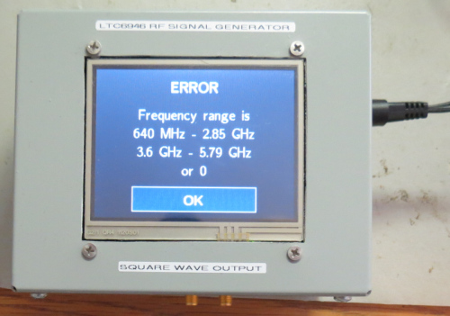
The basic premise of the application is there are 3 possible screens. The first displays the current frequency (which defaults to zero Hz at power-on). The second screen implements a keypad where the user can enter the desired frequency (including a decimal point). The third screen is an error message if an invalid frequency is entered.
A screen is built with widgets. This code uses two basic types of widgets. One is a canvas and the second is a button. Either can have text on them (or not), but a button can be pressed whereas a canvas cannot.
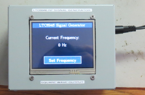
Each screen has a canvas background to clear the screen. Then the first screen has some canvases to display the current frequency, plus a button at the bottom which says “Set Frequency”.
Pressing that button causes the second screen to be drawn. Again a background canvas to clear the screen, then a bunch of buttons to permit entering the frequency. When the user enters the frequency, each digit is accepted as text and written into a string. The length of the string is checked – if it gets too long the user is shown the error screen. Other things, like removing leading zeros, excess decimal points, etc, are also handled as the user enters digits. One reason for treating input as a string is it makes it easier to echo the input on the screen as the user types. The keypad button handling is performed in the KeyPadPress () function. Apart from echoing the keypresses onto the screen, the speaker is also “clicked”, so the user is given lots of feedback.
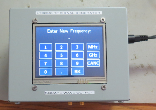
After the user presses one of the “final” buttons, namely MHz or GHz, the string is checked and then converted to an integer. It’s then checked against the acceptable frequency range, and if outside the range the user is presented the error screen.
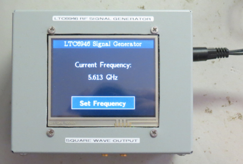
If the frequency is acceptable, the LTC6946 PLL register settings are calculated, then programmed into the chip via the SPI interface. This is done in the SetOutputFreq () function. If the frequency is zero, mute the output and exit. If the frequency is not zero, determine the appropriate output divider (from a table in the LTC6946 datasheet), then, knowing the reference equals 10 MHz, the output divider and the required frequency, we calculate the VCO ratio. To minimise glitches on the output, we mute the chip while reprogramming its registers, then unmute it when finished.
After that, we return to the first (current frequency) screen.
That’s pretty much it. The final screen is the error screen, there’s a photo earlier, and is mostly a canvas displaying the allowable frequency range (640 MHz – 2.85 GHz, 3.6 GHz – 5.79 GHz), with an OK button at the bottom which changes to the first (current frequency) screen.
Full software source code can be downloaded here. Or click on the retro floppy-disk picture to download.
![]()