
The desire is for this to be standalone – no PC, Alexa, etc required. Hardware requirements are pretty simple. Three modules, which can be readily and cheaply bought online, and two resistors. The modules are:
-
- An ESP32 development board. You can use an original Expressif board, or one of the many cheap clones. I used one with a WROOM-32 module on it.
- An Elechouse V3 voice recognition module. It comes with a microphone, not shown in the next couple of pictures.
- A little SSD1306 I2C connection OLED, 128 x 64 pixels.
In addition you need a 10k and a 4k7 resistor. The modules are wired together like this:
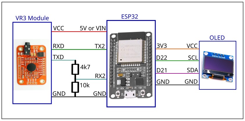
The ESP32 module powers both the Elechouse voice recognition module and the OLED. The OLED is powered from 3.3V, and the Elechouse module is powered from 5V (4.5V is actually what the ESP32 board provides). Depending upon the exact ESP32 board you use, the 5V output pin on the ESP32 board might be named 5V, or it might be named (somewhat confusingly) VIN.
The two resistors form a resistor-divider. The ESP32 is not 5V tolerant on its I/O pins, so the 5V-level TXD output pin from the Elechouse module must be divided down by the resistors to create a safe input level for the ESP32.
How you arrange the boards is up to you. This is what I did:
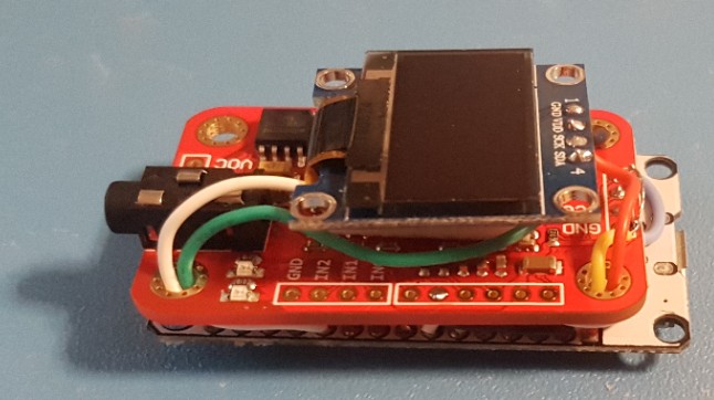
The ESP32 is on the bottom, with the WiFi module on that board facing down (ie facing outwards). In the middle is the Elechouse V3 voice recognition module, with the SSD1306 OLED on top. A few layers of double-sided-sticky foam tape were used to space the modules apart a bit, so they don’t short against each other, as well as to loosely stick them together.
My ESP32 module came with header pins attached, so first I had to remove them. This was performed by supporting the ESP32 board, gently, in a PCB holder or miniature vise or similar. Then gently but firmly pulling on a header pin while heating its solder joint. The heat from the soldering iron melts the solder joint obviously, but also softens the plastic of the header, allowing the pin to be pulled free. Repeat for all the pins. It works best if you heat the solder joint for about 3 seconds before starting to pull. With the header pins removed, it was then possible to wire the boards, and the two resistors, into this reasonably compact stack.
| << Introduction | Software Setup >> |