
The code is pretty simple, and is all written in C using the WinAVR (AVR GCC) free compiler. You can grab the DDS signal generator source code here:
![]()
Signal Generator Operation
This is what the unit displays when it’s first turned on:
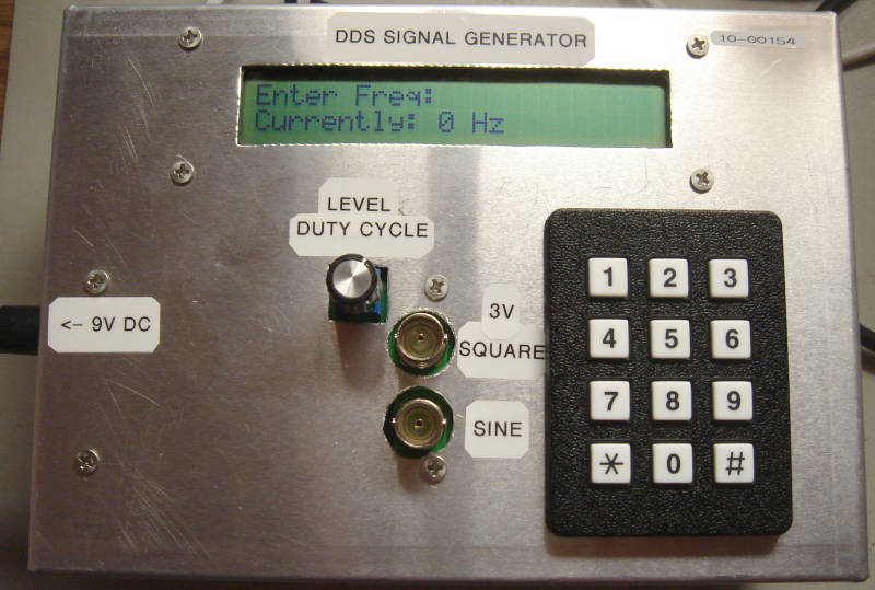
You can see it powers on generating a 0 Hz signal and it’s asking for a frequency to be entered. If the user starts entering a frequency in the keypad, the display changes, like so:

DDS signal generator
Notice that two things have happened. One, the numbers the user pressed are being displayed (as ASCII characters on the top line of the display). Two, the bottom line is now showing the “* and #” line to remind the user how to enter or cancel the current frequency.
Once the user hits “#” to enter the frequency, the display returns to this:
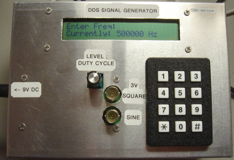
Where again it’s showing the current frequency on the bottom line, and inviting a new frequency to be entered on the top line.
At this point the code is just sitting in a loop, waiting for the user to press a number key to commence entering a new frequency.
While the user is entering a frequency, some limited error checking takes place. If the user enters too many numbers (too many keypresses) the unit displays an error message and returns to waiting for a new frequency. The user may never get to press “#” in this case. Also, once the user enters a frequency and presses “#” to enter it, the frequency is checked to make sure it’s within range before it’s accepted (and an error message displayed if its not). It’s possible for the user to enter 99 MHz for example, but the unit cannot generate that. The software cuts the user off at 40 MHz. The unit can’t really generate 40 MHz – the signal looks horrible as the DDS would only have about 3 points per cycle (144 MHz DDS clock remember). But it’s fun to try.
User frequency input is captured in a string as a series of ASCII characters which are also displayed on the LCD. Once the user presses “#” the frequency string is converted to an integer.
LCD Routines
Read this blog posting – it tells you all about the LCD code. In summary, the LCD is only written to (no reading from the display) in 8-bit mode, and simple delays are used for timing.
Part of me thinks it would be a good idea to write some code to put commas in the displayed frequency. For example: 1,000,000 Hz instead of 1000000 Hz. But it’s not exactly a big deal so I haven’t done it (yet).
Matrix Keypad Reading
The code contains routines for reading the matrix keypad. Google will quickly show you how to read a keypad, along with nice diagrams, but in summary, the keypad is assumed to be a 4×4 array. Four of the lines are set as inputs and pulled low using the Xmega’s internal pull-downs. The other 4 lines are set as outputs and set low. Then one-by-one each of the 4 outputs is set high (with the other 3 staying low) and the 4 inputs are read. If a key is pressed an input would read high, because the key would short an output line to an input line. If no key is pressed the 4 inputs would always read low.
The nice thing about this scheme is that if no key is pressed, we read everything as being low, ie, all zeros. A key pressed results in a non-zero number. Makes for easy coding.
These “keypad codes” are then converted to their corresponding ASCII character for display on the LCD, as well as for holding in the frequency string array (the string array of characters that the user typed in).
DDS Handling
This is heavily commented in the source, with references to the AD9851 datasheet. Basically the requested frequency is converted into a 32-bit magic number that the DDS chip requires to generate that frequency. Then another 8 bits are added on to that to create a 40-bit number (the extra 8 bits are control bits for things like enabling the x6 PLL). This 40-bit number is then written serially, one bit at a time, to the DDS, chip, at which point the DDS starts generating that new frequency.
The only bit of amusement here is that a small amount of 64-bit integer math is required to properly calculate that 32-bit magic number. It’s nice to see how easily the 8-bit Xmega can handle 64-bit operations, with the help of the AVR-GCC compiler.