
As you can see from the photos, it’s a simple metal box. Inside is two main boards, plus a little bit of power supply. Click on photo to enlarge.

A Texas Instruments / Luminary Micro Stellaris LM3S1958 development board, the RDK-IDM-L35, is the first main board, shown on the left of the photo. This board contains a colour 3.5” display with resistive touch overlay on its front side, and the LM3S1958 Cortex-M3 processor on the back side. This board is used unmodified. A brief overview of the board is here:
http://www.ti.com/lit/ug/spmu047/spmu047.pdf
Lots more information, including schematics, can be found here:
http://www.ti.com/tool/rdk-idm-l35
The second main board is the Linear Technology LTC6946 evaluation board, the DC1705:
http://www.linear.com/solutions/4085
I did consider building a PCB for this, however doing a PCB layout for multi-GHz signals is not always trivial. On the flip side, the LTC6946 eval board has almost everything I need, and what it doesn’t have is easily provided with some simple modifications. This board has two modifications. First, it needs a reference clock. A simple 3.3V 10 MHz oscillator pack was used to feed a clock into C6, the REF+ input on the IC. You can see it on the PCB, just below the “10 MHz” label on the board. Any 3.3V oscillator pack can be used, but the more stable & accurate the better, because this is the frequency reference for the board. The second modification is to change R13 to 10k, plus remove U4 and jumper its pins 3 – 4, to make it easier to hook into the SPI signals. As part of that, the test point labeled “V+DIG” is jumpered to +3.3V. This is to allow the remaining interface chips on the board to talk to the 3.3V processor board.
Finally, inside the box we need a small power supply. The Cortex-M3 processor board requires +5V, and the LTC6946 needs both +5V and +3.3V. There many ways to generate those voltages. I happened to have a couple of LM317 PCBs, so I used one to generate +3.3V and the other to generate +5V. You can see them mounted above the LTC6946 board. Their inputs are wired to a barrel connector socket mounted on the metal box.
Total power consumption at 9V input is around 340 mA.
Besides power, there are only 4 wires connecting the processor board to the LTC6946 board. These are the LTC6946 SPI signals: CS, CLK, SDI and SDO. They are connected to J2 (signals PA2 – PA5) on the TI processor board as follows:
PA2 – CLK
PA3 – CS
PA4 – SDO
PA5 – SDI
That’s it. A little bit of power wiring, just 4 wires for the SPI bus, and a couple of minor modifications to the LTC6946 demo board to give us the power & digital connections we need. Electrically this is very simple. I spent more time cutting holes in the metal box than wiring it up. Here’s what the SMA RF connections look like from the side.
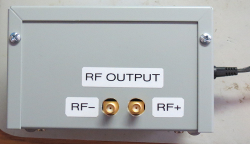
Note that the LTC6946 generates square waves, not sine waves. Hence there are harmonics present, if you care (you might not care, or you might want to filter them out). For most things I do, I don’t care, hence I don’t have any output filtering.
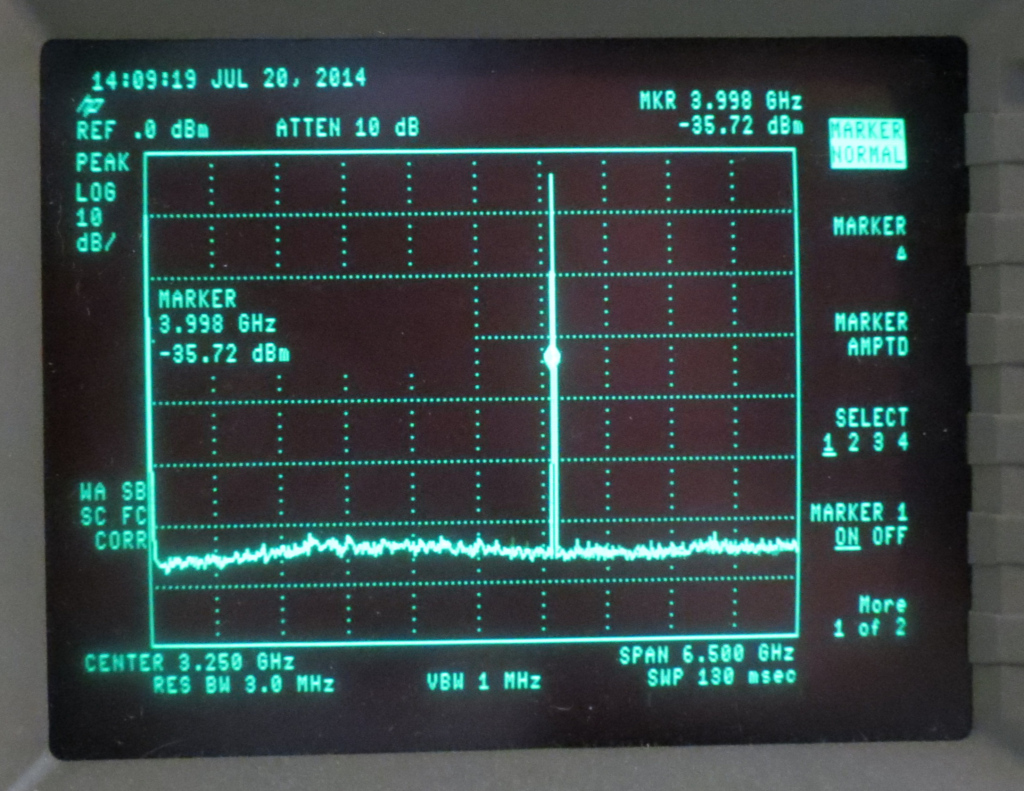
Now for some fun. Let’s hook it up to a spectrum analyzer. Both photos are with the generator set to 4 GHz. The first is with the spectrum analyzer set to full span (6.5 GHz in this case). Click on photo to enlarge.
The second photo is with a narrower span of 50 MHz, and a much narrower bandwidth. Again you can click to enlarge.
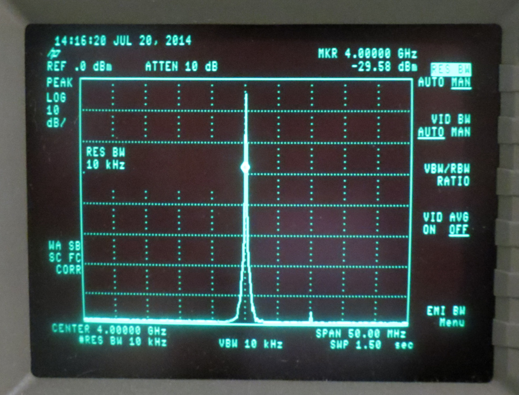
You can see the frequency accuracy is excellent, bandwidth is tight, and there are minimal spurs in nearby frequencies. The LTC6946 certainly appears to live up to its promises, and for our purposes makes for a nice, simple, frequency generator.