
The block diagram below gives a high-level view of the main components on the board.
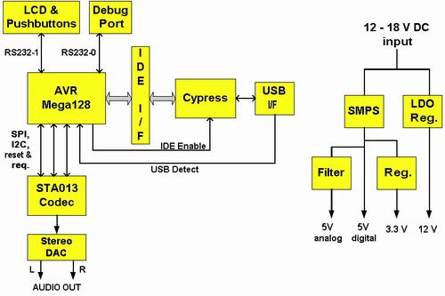
The following sections describe each major block in more detail.
AVR Microprocessor
The Atmel AVR Mega128 microcontroller is an 8-bit RISC-based processor running at 16 MHz. This is the heart of the player. Due to it’s architecture this device comes very close to achieving 1 instruction per cycle. Some instructions require 2 cycles, but the majority need only one. The result is that at 16 MHz, we have far more CPU power than we need, allowing plenty of CPU cycles for things like:
- Bus bit-bashing
- Sloppy coding 🙂
- Future expansion and features
Atmel’s AVR website is at:
http://www.atmel.com/products/avr/
The Mega128 has 128 kB of internal flash memory. This corresponds to 64k instruction-words, which is far more than is currently being used. There is a lot of extra space available for additional software features, display text strings, and so forth.
The device has 4 kB of internal SRAM. This is all the RAM on the board, so great care is required in its use. The majority of the RAM is used for buffering the MP3 files as they are pulled off the disk and fed to the codec. About 3 kB is used for this task, leaving about 1 kB for everything else. Given the large amount of flash memory on-chip, whenever a trade-off is possible between SRAM usage and flash usage, it always goes into the flash.
AVR In-System Programming
Connector J7 is a 10-pin header for in-system programming (ISP) of the AVR. This connector uses the pinout of the Kanda systems programmer, commonly known as the programmer dongle supplied with the STK200 and STK300 series of AVR development boards. Atmel shipped these boards for a long time. Both the STK200 and STK300 dongles have been tested with this board. PonyProg is an excellent shareware programmer with these dongles. It can be downloaded from:
http://www.lancos.com/prog.html
This website also has a schematic for the dongle if you want to make your own.
http://www.lancos.com/e2p/avrisp-stk200.gif
Here’s a photo of the dongle. It can say either STK200 or STK300; both types will work. On the left is the DB25 connector that plugs into a parallel port. On the right, hidden in this photo, is the 10-pin programming connector.
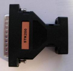
Recently Atmel has moved to a new ISP programming dongle (the AVR ISP, $34 from digikey) which has both the original 10-pin connector on it as well as a 6-pin connector. The signals are about the same; mainly the 6-pin just has fewer ground pins compared to the 10-pin header. Use the 10-pin header when programming the MP3 player. Unlike the Kanda programmer, the Atmel unit plugs into a USB port on the computer. That’s a lot more useful these days, with parallel ports going the way of the dinosaur.
Because the ISP programming pins are shared with the first UART and SPI port pins, a mux, U5, is used to control the routing of those shared pins. When pin 3 of the 10-pin header is disconnected or high, U5 routes the AVR’s UART and SPI signals to their respective player devices (LCD display and STA013 MP3 decoder). When pin 3 is pulled low those signals are routed to the 10-pin header to allow ISP programming.
Atmel also has a more expensive JTAG programmer. This requires separate pins routed to a separate connector, and is not supported on the player.
For more details on programming the Mega128, read this page.
IDE Interface
A very nice thing about the AVR is that almost all of its pins can be used as general purpose I/O pins (GPIOs). The IDE interface is constructed in this way. The IDE interface has a 16-bit data bus with some additional signals for address, chip-selects, read & write, reset, etc. These are all implemented as GPIOs on the AVR, with the bus timing signals generated by bit-bashing the appropriate GPIO pins. The interface is constructed as a simple PIO mode 1/2/3 read-write interface. No DMAs are supported, nor are they needed for the relatively slow MP3 file speeds.
Two IDE connectors are provided on-board. A 40-pin connector for standard 3.5” PC-type disks, and a 44-pin connector for 2.5” laptop disks. Note that you can only plug a single drive into the board at any time, and the drive has to be jumpered either as master, or as cable-select.
If you plan to use this player on a regular basis (as I do), harddisk selection should not be made purely on the basis of cost. I’ve experimented with several different drives. And have found that the amount of cache memory makes a significant different to the amount of seking the drive does. Older drives with 2 MB of cache tend to seek a reasonable amount. New drives with 8 MB of cache seek very little. I can highly recommend the Western Digital “Caviar” series of drives with the 8 MB cache. Note that the Caviar line has models with both 2 MB and 8 MB of cache; if you’re buying a drive for this player then get the 8 MB cache version. I’ve tested drives between 1 GB and 120 GB on the player. I’ve not tried drives larger than 120 GB. I know that the player won’t recognise capacities beyond 137 GB so I suggest you limit yourself to 120 GB maximum. That’s a lot of MP3’s!
If you’re re-using an existing drive, be aware that the player requires a FAT32 filesystem on the drive. As an example, if you’ve taken a drive from a WinNT system it’ll likely be formatted for NTFS so you’ll need to reformat it. (WinNT, XP, Linux, etc do recognise FAT32 drives however, making this a good generally-compatible file system.) OS’s such as Win98, WinME will format FAT32 by default. Read this for more information on diskdrive selection.
Debug Port
The second UART port on the AVR is routed through an RS-232 level converter to a female DB9 connector on the board. This is the debug port, and with a standard straight-through 9-pin serial cable can be connected to a PC runnning HyperTerminal or some such terminal program to display debug messages. Set the terminal program to 19200 baud, 8 bit data, 1 stop bit, no parity.
The debug port doesn’t do a huge amount functionality-wise. Its primary use is for spitting out debug messages during software development. Being able to do this is of great help during any code development. There is a simple debug menu; pressing the “?” key on an attached terminal will bring up a list of available commands.
LCD Display and Push-Buttons
This is Paul’s display and pushbuttons, from:
http://www.pjrc.com/store/mp3_display.html
This is a very attractive unit for a number of reasons. First of which is that it’s readily available; you can buy them right off his website. There are two versions; one with backlighting and one without. Either will work on this player. This player has a connector on the board for the backlighting (J10) which you can use as required to provide a software-switched 12V to power the backlight. Note that the backlight from Paul doesn’t have a power connector on it; I’d suggest you put a simple 2-pin connector on the wires to make it easy to plug into and out of this board. But you can just solder it straight into the PCB if you wish. If you can’t decide which display to buy, get the backlit one; it looks better in use.
The display and pushbuttons have a simple RS232 interface. The first UART port on the AVR passes through an RS232 level converter and then to connector J11 to connect to the display & buttons. Displaying characters on the display is accomplished by sending it commands. When a button is pressed by the user it sends back commands to the AVR. The protocol is described at:
http://www.pjrc.com/tech/mp3/lcd_protocol.html
With the backlighting on, or in a well-lit room, the decent size of the display characters allows viewing of the screen from a distance. It’s very suitable for a shelf-mounted player of this type.
STA013 MP3 Decoder & Audio Output
If the AVR is the heart of the player, then the STA013 is its soul. This chip is streamed an MP3 file, and it performs the decoding of the file, generation of the clocks and data signals for the stereo DAC, all with minimal supervision. Paul has written an excellent description of this chip here. ST’s website for the chip, including the datasheet, is found here.
There are two main ports connecting the STA013 to the AVR. The first is the I2C interface, which Atmel calls TWI. The Mega128 contains a TWI interface, saving me having to write bit-bashing code for it. This interface is used to configure the STA013, basically at power-up to get it into the correct configuration to do our bidding.
The second interface is the SPI port. Again the Mega128 contains an SPI port. From the AVR’s perspective this is a write-only port, and is used to give the MP3 file to the STA013. The STA013 has a separate DATA_REQ line, which it uses (sets high) to signal that it wants more data. When the AVR sees the data request line active, it sends another byte over the SPI port.
The STA013 generates all of the clock and data signals required for the 24-bit stereo audio D/A converter, U7. The audio outputs are then filtered to remove any digital noise and fed to the RCA audio connectors. U7 and the filtering components have their own audio power supply and audio ground plane for the lowest possible noise floor.
Unfortunately the STA013 is a 3.3V device and is not 5V tolerant. This means any signals driven by the AVR to the STA013 must be current-limited. Resistors R16, R34, R35 and capacitors C27 & C28 perform this “protection” circuitry whilst allowing the fast edge transistions through. During the design of the player I spent some time considering “what if I ran the AVR off 3.3V?”. With the hope that doing so would remove the need for these components. Unfortunately then the AVR, while happy to run off 3.3V, would then itself be 5V intolerant, causing a problem with the IDE interface, which is a 5V interface. So that idea didn’t work out, and we have 5 extra components on the board (3 resistors and 2 capacitors) as a result. For those who might be wondering, the Cypress USB 2.0 part, although running off 3.3V, is 5V tolerant and so doesn’t have this problem.
InfraRed Remote Control Port
U8 is an IR receiver part. Its output is connected to the AVR via one of it’s GPIO / interrupt lines. The idea being that a standard remote control can be used to control this player. This part is not a “decoder”. All it does is detect and demodulate the IR signal, resulting in a square wave, not too different to what you’d see from a UART, on it’s output. AVR software then times the transitions of this serial bitstream to determine which remote-control key was pressed.
USB 2.0 Interface
My original prototype had a USB 1.1 interface, but I found that to be too slow for transferring large numbers of MP3s to the player. The current board has a USB 2.0 interface, which is very satisfactory.
USB 2.0 is implemented using a Cypress IDE Mass-storage class device, the EZ-USB AT2 device (part number CY7C68300A). This chip contains the full USB protocol stack compliant with the mass-storage class specification. What this means is that when you plug the player into your PC, the drive on the player automatically pops up as a drive under Windows Explorer (in Windows OS’s; should be similar in Mac and Linux OS’s). No special drivers required (except for Win98). You can then drag and drop files to the player.
USB 2.0 is backwards compatible with the much-slower USB 1.1. If you plan to shift a reasonable number of files using an older PC however, I’d recommend putting a USB 2.0 PCI card in your PC first. They’re cheap and dramatically faster than USB 1.1
A “USB detect” signal is monitored by the AVR so that it knows when the user plugs in a USB cable. This is the USB_5V signal. It works simply by detecting the 5V voltage present on the USB cable coming from the host PC. When it sees this the AVR jumps off the IDE bus (tristates its IDE signals). It then asserts (pulls high) the USB_ENABLE signal, informing the Cypress part that it’s permitted to access the IDE interface. This scheme ensures there is no contention for the IDE bus between the AVR and the Cypress USB 2.0 part.
A very important consideration with USB 2.0 is PCB layout. Particularly the routing of the USB signal pair itself. The USB specification recommends at least a 4-layer PCB to ensure good impedance-matched traces. For cost reasons this player uses a 2-layer PCB. The USB trace pair is kept short, routed together and routed over a ground plane to control the impedance as closely as possible. Ground traces are also run beside the USB traces, and no vias are used. All of these efforts should result in a reliable USB link. Testing to date certainly appears to validate this; the link has shown no problems.
The programmable parameters for the USB 2.0 interface are contained within U9, a small serial eeprom. For details of these parameters, refer to the CY7C68300A datasheet. For the programming file and details on how to perform the programming, refer to my USB 2.0 page.
Cypress’s website is: http://www.cypress.com
The use of the Cypress part means that no USB programming is required; it’s all internal to that chip. The part performs a full USB-to-IDE implementation; all that’s required from the AVR is to monitor the USB port and enable or disable the Cypress part. Not having to write a mass-storage class interface, or a PC driver, saves a tremendous amount of work.
For those reading the CY7C68300A datasheet, here’s a clarification I received from Cypress technical support. In the datasheet “absolute maximum ratings” section it states that the maximum DC voltage that may be applied to output pins in the high-Z state is VCC+0.5V. Given that VCC is 3.3V, this would be 3.8V. However the IDE specification allows 5V signalling, so it appears from the datasheet that this part does not meet IDE spec.
This is not actually the case; Cypress tech support informed me this is an oversight in the datasheet. That parameter only applies to non-IDE pins. The IDE pins are all rated for 5V tolerance, even when they are tri-stated. They also pointed out that the reason for this parameter in the datasheet was to prevent designers from powering-down the chip when it’s not in use. This would not work; the chip could be damaged if VCC=0V with 5V on its IDE pins. In the design of this player the CY7C68300A is always powered up so there is no concern about damage to the part.
Power Supply
For details on power-supply selection to power the player, read this page.
This player accepts a DC supply in the 12.5 – 16 volt range. This voltage range was chosen to allow operation from a car battery. A low-dropout linear regulator U1 generates the 12V required for the disk drive as well as the LCB backlighting. (I have not tested the player in a car; if you’ve tried it please let me know how it went.)
A buck topology step-down switchmode power supply U2 and related parts generates 5V for the AVR as well as for U7 the stereo DAC. +5V is also required for the LCD display and pushbuttons, and the disk drive. The transil (or tranzorb), D1, provides overvoltage and reverse-polarity protection. Essentially just an overgrown zener diode, it’ll conduct if the voltage is too high (above 17 volts or so) or if the polarity is reversed. If the power fault is severe enough that’ll cause the fuse F1 to blow. Either way the player gets a reasonable amount of protection. This is important in a car where the 12V power can get pretty nasty during engine starts and stops. It’s also nice during development because, as we all know, accidents can happen, and you don’t want an accidental reversed polarity to destroy your player.
The small linear regulator U3 generates 3.3V from the 5V to provide power to the Cypress USB chip and the STA013 MP3 decoder chip.
Ground planes are poured on the PCB as much as possible. This is most noticeable around J3 and J4, the RCA audio connectors, where an isolated audio-ground plane exists on both sides of the PCB to maximise audio quality. Filters L2 and L5 are used to provide that power and ground isolation to make this possible.
Digital ground pours are common on the rest of the PCB. These act to reduce the ground impedance and improve signal integrity. Ground pours are also used around the power-supply components to act as a PCB heatsink.