
This section provides information on construction and testing of the kit MP3 player. For notes on selecting a powersupply, read here.
Be Static-Aware
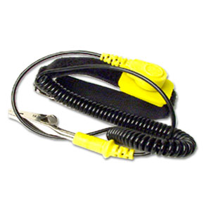
You’re building a board using components that are very vulnerable to static damage. Be careful!! Wear a wrist strap. Reach over and touch something metal and grounded. Please don’t wear a polyester suit whilst shuffling your feet on the shag carpet… 🙂 Make every effort to avoid static buildups – static WILL kill your project. Use that wriststrap! They look a lot like this:
Starting the Build – General Notes
Start with a visual scan of the PCB. Make sure it’s clean and doesn’t have any little bitties stuck to it. Particularly between the pins of the already-soldered surface-mount devices. Look for any obvious problems. I always like to pull out my multimeter and check there are no shorts between any of the voltage rails and ground. Get comfortable with the schematics (circuit diagrams); they are your friends. They help tell you what parts go where.
Be careful with capacitor polarizations. It can be confusing with some of the small electrolytic and tantalum capacitors when the silkscreen overlay gets busy. When in doubt, it will help you to know that on the PCB, the square pin pad is the positive terminal of the capacitor. So a polarized capacitor, which has two pads on the PCB, will have a square pad for the + lead, and a round pad for the – lead.
Read this entire assembly guide before soldering down any components.
Start with the Low-Profile Parts – Follow the Bag Numbers.
There are three bags of components, numbered 1 through 3. Bag 1 contains low-profile non static-sensitive components. Start with these. Note that you are soldering them into a PCB which already has surface-mount ICs soldered onto it, so take all static precautions.
You’ll note that some resistors lay flat on the board, while others, such as those sandwiched between the two IDE connectors, stand up. All resistors are 5% tolerance except for the 24k and 2k7 which are 1%. These set the 12V voltage, so don’t substitute them.
Take care with your component placement. Accidently inserting a capacitor backwards, or a resistor in the wrong spot, is very easy to do but will cause you no end of grief. Double-check each component’s value, location and orientation before soldering it. A few extra minutes spent double-checking yourself during construction can make the difference between a working player and a “silly error” dead one. Some silly errors can get expensive; a mistake building the power-supply could easily fry the chips on the board, the LCD display, and / or your disk drive! So be careful and constantly double-check your work as you go along.
There are numerous tantalum capacitors on the board. The black bar on the casing indicates the +ve (positive) lead.
R32 (next to the USB connector) is a zero-ohm resistor. In other words it’s just a straight wire link. Use a piece of wire you’ve previously snipped off a resistor or capacitor for R32.
Once you’ve finished soldering all of the components from bag 1, move on to bag 2. This bag contains some static-sensitive parts such as some ICs, diodes and transistors, but like bag 1 these are also lower-profile parts. Bag two also contains some components that could otherwise be easily confused with components in bag 1, such as the nonpolarized electrolytic capacitors C18 & C19, and the small “resistor-like” inductors L2 – L5. For this reason be careful not to mix up the contents of the different bags.
Finally, once bag 2 is complete, bag 3 contains the tall components. These are mostly connectors, although C1 (the large electrolytic capacitor) is also in this bag.
Resistor Colour Codes
If you don’t know how to read those colourful resistors, here’s an excellent description for the common 5% tolerance resistors:
http://webhome.idirect.com/~jadams/electronics/resistor_codes.htm
Most of the resistors in the kit are 5% tolerance. A few are 1% and read slightly differently. Read about those here:
http://www.technology.niagarac.on.ca/courses/etec1120/Files/resistor.pdf
The labels on the kit bags include the resistor colour codes to make your job a little quicker.
Capacitor Values
Small capacitors read similarly to resistors but without the colours; they just use numbers. The first two are digits and the third is a multiplier, with the result expressed in pF. So, a capacitor with 104 written on it is: 10 0000 pf, which is 100 nF which is 0.1uF. A 22 pF capacitor would normally read 220, although sometimes the manufacturer just writes 22.
There are a number of small capacitors for this project, beyond the handful of 0.1uF decoupling capacitors. Sort through them and ensure you know which is which before soldering them down.
Optional Parts
D1, the tranzorb, is only required if you plan to use the player in a harsh power environment, such as in a car. In conjunction with the fuse it provides both overvoltage and reverse-polarity protection. If you’re going to run the player in your home off a plugplug you shouldn’t need D1. Having said that, I recommend you install it, just in case you accidently connect power backwards. D1 can make the difference between replacing a fuse and replacing the board.
J8, the DB9 debug connector, is only required if you plan to do some software development. If you write code for the player you’ll find the debug port useful for printing status or error messages. If you don’t plan on being a “code monkey” you can leave this connector off. You’ll need to be “firm” to make the spring clips on each end of the connector click into the PCB. Be careful, but be firm.
LED, LCD Backlighting, and InfraRed
I suggest putting small connectors in the board for D4 (the LED), U8 (the infrared receiver) and J10 (power for the LCD backlight). You will likely attach all three of these devices to your front-panel in some semi-permanent way. In my case I’ve glued the LED and infrared receiver into holes in my box front panel, and the LCD backlight is (of course) on the LCD which is bolted in. Having connectors on the PCB for their leads makes it easy to remove the PCB from its enclosure without having to do any painful disassembly. Exactly how you do it is up to you, but the hole size for these components is chosen to make it fairly easy to do. The kit contains both male & female connectors for this purpose.
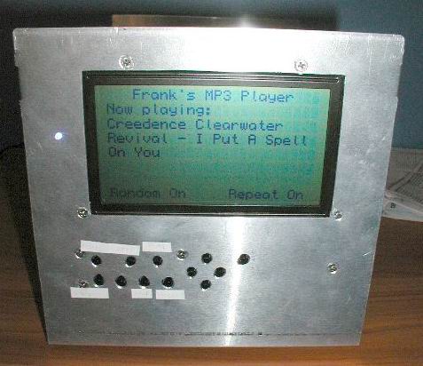
The photo below provides a rear-view of the LCD display and pushbuttons mounted in a simple panel. The LED can also be seen, with it’s red & black wires. I used a blue LED because it’s fun, but you can pick any colour you want. It’s just glued in there. The LCD display and pushbutton PCB are simply bolted in to the panel. On the left you can see the grey ribbon cable interconnecting the two PCBs. This particular LCD in the photo doesn’t have a backlight, so don’t bother peering at the photo too hard looking for it.
Be careful with your connector orientation for the LED and the IR receiver. In the kit I provide polarized connectors for these parts so you can easily make up a little cable appropriate for your enclosure. Be certain that when you make your cable you get the wires the right way around; you don’t want to power the IR receiver backwards! That’ll kill it for sure. Wiring instructions for the IR receiver are below.
IDE Connectors J5 & J6
The kit contains two IDE connector headers:
- a 40-pin 0.1″ spaced header for J6 which is used for 3.5″ disk drives (regular PC disk drives), and;
- a 44-pin 2mm spaced header for J5 which is used for 2.5″ laptop drives.
Only install the one header that you need. Do not install both unless you actually need to swap between two different disk-drive types. (Note that you can only have one diskdrive plugged into the player at any one time.) When one connector is cabled to a disk drive the other connector, if present, acts like a stub on the IDE bus, reducing the quality of the IDE bus signals. To avoid this stub effect, only populate the one IDE connector that you need.
If J6 (the 40-pin header) is used, remove pin 20 from the header before soldering it into the board (kit connectors normally come with this pin already removed). This allows the use of an Ultra-IDE diskdrive cable, which is the cable with the extra ground wires in it. Just out of interest, take a look at the IDE connector on your 3.5″ diskdrive: on any remotely modern drive you’ll see that pin 20 is missing there too. (That’s also a good way to double-check which pin is pin 20 before puling it out of the header.)
J7, the ISP Connector
This is a simple 10-pin header. Use the keyed version (ie the one with the little notch cut out the side). It’s oriented on the PCB to allow use of a right-angle version. If you use a right-angle connector you can have it poke out the rear of your box, allowing you to reprogram the player without even having to open the box. Recommended, and this is what is provided in the kit.
The RCA Connectors & Fuseclips
Fiddle with the two RCA audio connectors a little before soldering them down. Make sure you know how they best mount on the PCB. They will sit flat on the PCB; they shouldn’t be pointing up at all.
The fuseclips are a little trickier. Make sure you have them the right way around! Otherwise your fuse won’t clip in. Oops. You may find it easier to mount a fuse in them, then solder that whole little assembly down. You may find it easiest to lightly solder the fuseclips from the top of the PCB while you hold them upright. Then once they’re standing straight of their own accord you can flip the board and solder them in properly from the bottom of the PCB.
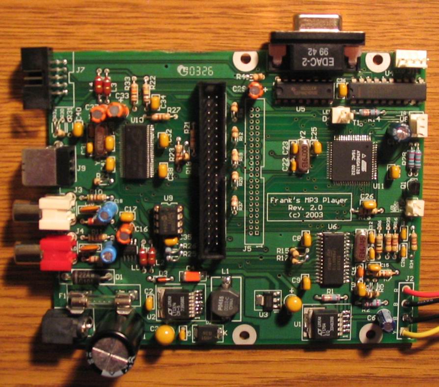
The Assembled PCB
The photo below is of an assembled rev 2 PCB. Those with sharp eyes may notice a resistor missing towards the top left of the photo. (OK, so it’s not completely assembled!). This photo should give you an idea of what the end product may look like. Click on the photo for a larger view.
Disk Drive Power
If you use a 3.5” drive you’ll be using power connector J2, as well as IDE connector J6. If you use a laptop drive you won’t need power connector J2, as the laptop drive draws its power from IDE connector J5.
J2 is a standard disk-drive power connector on short (two or three inches) wires. Where to get one? If there’s a PC being junked anywhere, snip a connector off its power supply. Alternatively, go to your local computer store and purchase a “Y” disk-drive power cable. This is a little cable that breaks a single power-connector into two. One of these gives you two disk-drive power connectors.
Remote Control Receiver
The 3-pin IR receiver is labelled U8 on the schematics and PCB. Although you can install it directly into the PCB, most people will want to have it on a length of wire so that the receiver chip can be glued into the front of their case. For this reason the kits provide a 3-pin male and female connector to make this easy.
The IR receiver used is now the Vishay TSOP1238 receiver. Which pin goes where? The picture below shows its pin numbering.
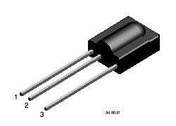
Connect it to the U8 3-pin connector on the mp3 player as follows:
U8 pin 1 = OUT (IR receiver pin 3)
U8 pin 2 = GND (IR receiver pin 1)
U8 pin 3 = Vs (IR receiver pin 2)
U8 pin 1 is the pin closest to R28.
It’s that simple: 3 wires and you’re done. The actual receiver part of the chip is that long rounded bump on the front of the chip; that’s the part you’ll want facing out of your case. Bending its leads is OK. Like any IC just try to be static-safe while you’re handling it.
Mounting on a 3.5” Drive
The four big holes on the board line up with the mounting holes in the bottom of a 3.5” drive. Yes, it’s fine to run the drive upside down; drives don’t care. The board is laid out so that the end with the audio, power, USB etc connectors overhangs the end of the drive, to allow these connectors to poke through the back of your box without having to run any messy wires.
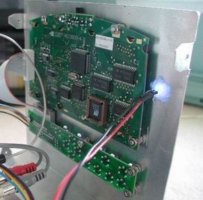
I’ve found that the player seems to be happier if there’s a metal shield between it and the drive. I suspect that noise radiating from the drive sometimes affects the player. I cut a little piece of metal flashing from the local hardware store to size, drilled 4 holes in it, and installed it between the drive and the PCB. Using threaded standoffs made it pretty simple. See the Rev 1 mounting photo below.
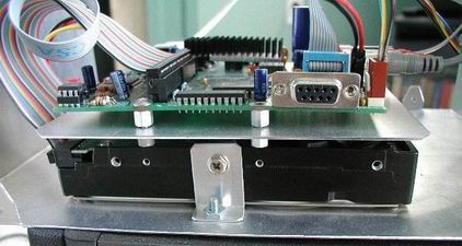
The black thing on the bottom is the drive. You’re looking at it side-on. It’s bolted to the box floor with the help of a bent piece of metal. Threaded standoffs are used to mount a metal sheet above the drive. You’re looking at that edge-on. Then another set of standoffs to support the PCB. The colourful ribbon cable on the left is the IDE cable. You can see that the assembled drive, metal shield and PCB makes a neat and simple self-contained “brick” for bolting down into a box.
Here’s a photo from the front of an LCD (non-backlit in this case) and pushbuttons mounted in a simple panel. The panel has a rectangular hole cut in it for the LCD and some drill-holes for bolting everything in as well as allowing the pushbuttons to protrude through. Not a great photo but you get the idea:
Powering Up The Board
Now that you’ve soldered in all of the components, it’s time to power up. Do a careful double-check of everything. Take your time. If you’ve made a mistake, better to find and fix it now before you power up and smoke something. Good light and a magnifying glass can be helpful. If you built from a kit there should be no empty component spaces on the PCB, with the exception of one of the IDE connectors. So if you spot an unpopulated resistor or capacitor site you’re guaranteed to have missed something.
Disconnect any cables, except the LED (if you have it connected; no big deal either way). Make sure you have the drive, LCD display, etc all disconnected. In the event of a bad fault you don’t want to damage them. Double-check with your multimeter that your power supply puts out a suitable voltage (12.5 – 16 volts DC) and that the polarity of its connector is OK (centre is positive, outer barrel is GND). Once you’re happy it’s time for the moment of truth. Plug in your power-supply and switch it on. No smoke I hope! Use your multimeter to check the voltages at the disk-drive power connector. Black is GND, red should be +5V and yellow should be +12V. Any problems, power down immediately and check your board again.
For more details on powering the player, read this.
Leaving your multimeter GND lead on the GND connection, check the tab on the little 3.3V regulator U3. It should be 3.3V. Probing around its pins you should find 5V going in, and 3.3V coming out. Also check the power coming into the board (the fuse clips are a good spot) – the voltage should be between 13 and 18 volts.
If that’s all OK, power down. If you’re using a 3.5″ drive, plug in its’ power connector only. Not the IDE ribbon cable; only its power. Then power-up again and recheck the 5V and 12V rails. If you’re using a laptop drive, skip this step. You don’t want to plug in the IDE cable until you’ve programmed the AVR. Power down.
Programming the AVR
With the various board voltages checked out OK, it’s time to program the AVR. Exactly how you do this depends upon what programming dongle & programming software you’re using. Read your documentation. Most likely it’ll be a 2-step process. Once you’ve hooked up the programming cable and powered-on the board you’ll want to program the “fuse bits” in the Mega128. This will do useful things like take the AVR out of Mega103 compatibility mode and enable the 16 MHz crystal oscillator. See the readme.txt file in the software zip file for details. Once you’re happy with the fuse bits settings, you can then go and program the part with the MP3 player software. Double-check those fuse bits! If they’re wrong all kinds of wierd things can happen. For example the LCD display working but the debug port not, due to being in Mega103 mode. Or nothing working because the AVR is running off its slow internal RC oscillator instead of the 16 MHz crystal.
Once the AVR is programmed and verifies, power-down and unplug the programming cable. Now plug in everything else! The LCD display; the LED, the drive power & IDE ribbon cable, etc. Strictly speaking you don’t need to plug in the audio connectors yet, but you can if you want to. Then power-on.
What should happen is the LED should light. After a brief delay (a couple of seconds) the LCD display should start displaying text. The drive will be audibly winding up, and then the player will tell you (on the display) it’s counting MP3 files and building tables. Once it finishes this you should be able to press the play button to start playing the first MP3 file. Assuming there are files on the drive of course. Congratulations!
This was the short version of programming the AVR. For a more detailed version read this page.
Downloading Files
Once you plug the USB cable in (connected to your PC) the LCD display will show that it’s been detected and hands off control to the USB interface. At that point you can format the drive (if need be; yes apparently you can do that over USB, although I’ve not done it personally) and of course drop MP3 files into the player’s root directory.
Hot Power Supply or USB Chip?
Depending upon the drive being used and the voltage provided to the player, the 5V switchmode regulator and the 12V linear regulator may get a little warm. The only way to find out is to run the player and carefully touch the power-supply components (with your fingertip, wearing a wriststrap of course :-). Check them every 20 seconds or so to see how quickly they heat up. If they get really hot you need to put a heatsink on them. I purchased a small stick-on heatsink from my local electronics store and cut it in half (because it was too wide) then stuck it on the chips. That helped a lot. Given that the player sits on the shelf and doesn’t move around, the sticky backing held the heatsink on just fine. This is something you’ll find by experimenting, depending upon how much power your drive draws and the voltage your power-supply provides (higher voltage power-supply equals hotter U1 & U2). Excess heat will kill the chips, so check them and heatsink them if necessary. Or put some diodes in series with the power supply, so that the input voltage to the board is lower. As described here.
Similarly with the USB chip. It can dissipate close to 1W of power. Keep an eye (finger!) on it, and if you’re at all concerned, put a small heatsink on it. Whether you need it or not will completely depend upon how much you use the USB port. If in doubt, put a small heatsink on it; you don’t want to fry that chip. If the USB chip gets hot then most likely the little 3.3V regulator U3 will be also, so you may need to place a small heatsink on it as well.